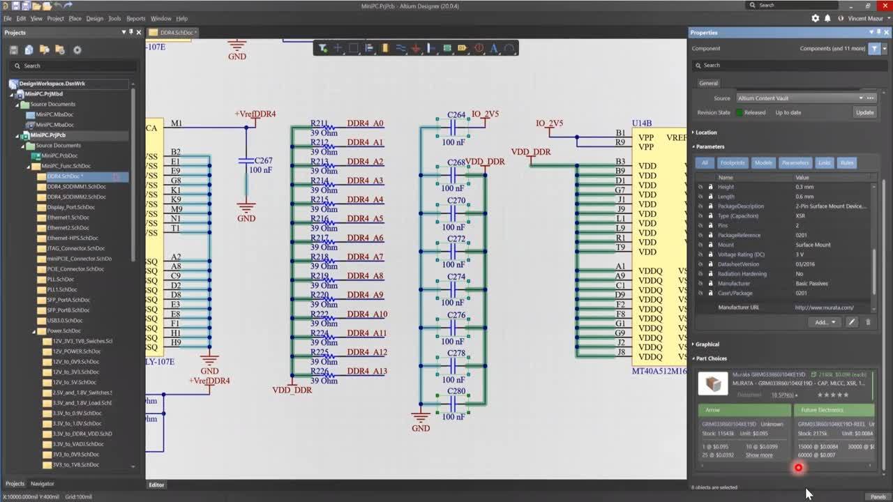

If you need you can do finer traces (I use down to 6 mils on the Modela), but try to keep them wide for now.Some time ago, Elektor started using Altium Designer 6, after working for years with Cadence OrCAD for schematics and Ultiboard for PCB design. A general rule of thumb is to use the same spacing for traces and clearance (so 16 mils in that case).As a general piece of advice, never trust anything that comes free from the Internet.It's good for a 10 mils endmill, not for the one you'll be using. Some versions of the fab.dru file have 0.315mm for the clearance.Here's a 17 mils DRU file for you: fablab_17mils.dru. You should use a clearance of AT LEAST 16 mils. DRC: You will be milling your boards with the 1/64 endmill.Adjust the Outline to be slightly bigger than the circuit.

The DRC will tell you if your board can by milled or not. Use 'fab.dru' (it's in the archive, right next to fab.lbr) as your design rule file. When you are done routing make sure to run a DRC (Design Rule Check).When possible, avoid right and acute angles.Will people be able to understand what's going on? Using a frame (the same size as your sheet), clear names, un-tangled wires and comments will make it so much easier for someone reading it. Keep in mind that at some point your schematic will be printed in black and white.If you connect it across +5V and GND you will short your power supply when you press on it. Use the 'Show' tool to highlight your nets and make sure that what you think is connected truly is.It's good practice to draw your schematic in a frame.When you place a resistor such as 'RES-US1206FAB' it doesn't have a value.

Do not mix names (I've seen some schematic where the +5V symbol was linked to a net names 'VCC'). For VCC/+5V & GND use the symbols from the 'supply1' lib.Read this Sparkfun tutorial and check Charles' design for examples. It's really hard to read a schematic with only wires, or with only net names. Now that I have reviewed some of your schematic and PCBs I can summarize the most common issues. "A how-to guide to taking your electronics project from prototype through to high volume PCB manufacture." The Engineer’s Guide To High-Quality PCB Design Good overview of the design process, lots of picturesĪltium Designer Tutorial: Schematic capture and PCB layout Note that Sparkfun provide free libs for the products they sell.

Trace? Via? Silkscreen? Gerber? Double-sided PCB? All the answers are on this link.Įxcellent tutorial if you want to use EAGLE. This tutorial will breakdown what makes up a PCB and some of the common terms used in the PCB world." It’s so fundamental that people often forget to explain what a PCB is. "One of the key concepts in electronics is the printed circuit board or PCB. Scroll down to see the class specific FAQ and to get the DRU file. Here's some information regarding PCB design.


 0 kommentar(er)
